Meteorological environment monitoring equipment supplier
Insist on doing high-precision customer favorite technology products

Meteorological environment monitoring equipment supplier
Insist on doing high-precision customer favorite technology products

1. Introduction to cems flue gas monitoring system project
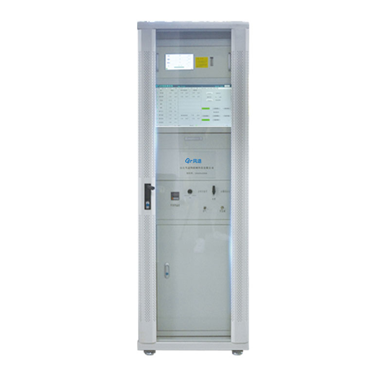
According to your measurement requirements, the cems flue gas monitoring system is also known as the flue gas emission continuous monitoring system and flue gas emission automatic monitoring equipment. The cems flue gas monitoring system is an environmental monitoring equipment used for real-time online monitoring of harmful polluting gases. The FT-CEMS-1000 flue gas emission continuous monitoring system launched by Fengtu Technology can continuously monitor SO2, NOX, 02 (standard, wet basis, dry basis and converted), particulate matter concentration, flue gas temperature, pressure, flow rate, etc. related parameters, and statistics on emission rates, total emissions, etc. Thus the measured data can be effectively managed.
The FT-CEMS-1000 system consists of four required subsystems: gaseous pollutant (SO2, NOX, 02, etc.) monitoring, particulate matter monitoring, flue gas parameter (temperature, pressure, flow rate, etc.) monitoring and data acquisition and processing.
The gaseous pollutant monitoring adopts the extraction condensation method. The principle is to use the ultraviolet differential method to measure the SO2 and NOX content in the flue gas, measure the wet oxygen content through the electrochemical method, and then calculate the dry content of SO2, NOX, and O2 through dry-wet conversion. Smoke concentration.
The particulate matter monitoring uses the laser backscattering method, the temperature of the flue gas is measured by a temperature sensor, the flue gas pressure is measured by a pressure sensor, and the flue gas flow rate is measured by a pitot tube; all measurement signals are sent to the data acquisition and processing system.
The output processing system has functions such as real-time transmission of on-site data, remote fault diagnosis, report statistics, and graphic data analysis, enabling unattended work sites. The entire system has a simple structure, wide dynamic range, strong real-time performance, flexible networking, and low operating costs. At the same time, the system adopts a modular structure and is easy to assemble. It can fully meet the requirements for communication with the internal DCS system of the enterprise and the data system of the environmental protection department. .
000011 Project Execution Standards
The design, manufacturing, and acceptance specifications of this system are mainly carried out in accordance with the following standards and technical specifications:
u GB3095-1996 "Atmospheric Environmental Quality Standard"
u GB13223-2003 "Emission Standards for Air Pollutants from Thermal Power Plants"
u GB18485-2007 "Control Standards for Pollutants from Domestic Waste Incineration"
u HJ/T75-2007 "Technical Specifications for Continuous Monitoring of Flue Gas Emissions from Thermal Power Plants"
u CJJ90-2002 "Technical Specifications for Municipal Domestic Waste Incineration Engineering"
u CJ/T118—2002 "Technical Specifications for Municipal Domestic Waste Incinerators"
u HJ/T76-2007 "Technical Requirements and Detection Methods for Continuous Monitoring Systems for Flue Gas Emissions from Stationary Pollution Sources"
u GB16297-1996 "Comprehensive Emission Standard of Air Pollutants"
u GB/T16157-1996 "Methods for determination of particulate matter in exhaust from solid pollution sources and sampling of gaseous pollutants"
u GB9078-1996 "Comprehensive Emission Standard of Air Pollutants for Industrial Kilns"
u GB 3095-1996 "Ambient Air Quality Standards"
u GB12519-1990 "General Technical Conditions for Analytical Instruments"
000012 Project Plan
000012.1 Measurement items
Ø SO2, NOX, O2, smoke, temperature, pressure, flow rate
000012.2 Measurement method
Ø Flue gas sampling method: extraction condensation method
Ø SO2, NOX monitoring method: differential optical absorption spectrometry
Ø O2 monitoring method: electrochemical method
Ø Smoke measurement method: laser backscattering method
Ø Temperature measurement method: temperature sensor
Ø Humidity measurement method: Humidity sensor
Ø Pressure measurement method: pressure sensor
Ø Flow velocity and flow measurement method: Differential pressure method (Pitot tube)
2. System General Principles
The functional design, structure, performance, installation and testing technical requirements of the CEMS flue gas monitoring system all comply with the relevant national environmental protection standards and meet the environmental protection industry of the People's Republic of China (HJ/T75-2007, HJ/T76-2007 )standard requirement.
The company's CEMS system consists of a gaseous pollutant monitoring subsystem, a particulate matter monitoring subsystem, a flue gas parameter monitoring subsystem and a data acquisition and processing subsystem. The gaseous pollutant monitoring subsystem and data acquisition and processing subsystem are installed in the standard Inside a 19-inch cabinet. The system composition is as follows:

Figure 1. CEMS system composition diagram
Ø Gaseous pollutant monitoring subsystem: composed of sampling unit, pretreatment unit and analysis unit.
Ø Particulate matter monitoring subsystem: using laser backscattering smoke monitor.
Ø Flue gas parameter monitoring subsystem: Pitot tube is used to measure flow rate, pressure sensor is used to measure pressure, temperature sensor is used to measure temperature, and flue gas humidity is measured using high-temperature capacitive humidity sensor.
Ø Data acquisition and processing subsystem: composed of data collector, industrial computer, display and system software.
The above subsystems are tailored according to different customer needs.

Figure 2. CEMS system installation diagram
3. System composition
3.1 Monitoring of gaseous pollutants
3.1.1 Sampling and preprocessing unit
The sample gas is taken out by the sampling probe under the force of the sampling pump. Most of the particulate matter in the sample gas is filtered out by the filter in the sampling probe. After filtering, it is transported to the refrigeration system by the heating pipeline to condense and remove water, and then sent to the analysis unit for analysis. The condensed water is drained away through the drainage system. The control unit implements functions such as backflush, calibration, and refrigeration temperature alarm prompts, and displays various working states of the system.

The pretreatment system uses one-stage rapid condensation to remove water to ensure that the gas composition remains unchanged. Two-stage fine filtration is used to ensure that the gas measurement chamber is not contaminated, thus extending the service life of the analyzer. The figure below is the flow chart of the gaseous pollutant monitoring system.
3.1.2 Gas analyzer
Instrument: UV Spectroscopic Gas Analyzer
Model: FT-UVA-100
Measurement principle: Differential optical absorption spectroscopy (DOAS)
Measurement principle
The UV spectrum gas analyzer is a gas analysis instrument based on multi-channel spectral analysis technology (OMA) and differential optical absorption spectrometry (DOAS). The light beam emitted by the light source converges into the optical fiber and is transmitted to the gas chamber through the optical fiber. After passing through the gas chamber, it is absorbed by the gas to be measured and then transmitted to the spectrometer by the optical fiber. It is split by the grating inside the spectrometer, and the array sensor converts the split optical signal. As an electrical signal, the continuous absorption spectrum information of the gas is obtained. The instrument uses differential absorption spectrum algorithm (DOAS) and partial least squares algorithm (PLS) to process based on this spectral information to obtain the concentration of the measured gas.
Ø Multi-band spectral analysis technology (OMA)
Since various gas molecules absorb light waves differently in different wavelength bands, simultaneous measurement of multiple gases can be achieved by analyzing the continuous spectrum after gas absorption.

The UV spectrum gas analyzer uses a light source and sensor in the ultraviolet band to measure the concentration of gases that absorb light waves in the ultraviolet band, such as SO2, NO, NO2 and other gases.
Ø Differential optical absorption spectroscopy (DOAS)
The core idea of DOAS is to decompose the absorption spectrum of gas into two parts: fast changing and slowly changing parts. The fast-changing part is related to the structure and elements of the gas molecules, and is the characteristic part of the gas molecule absorption spectrum; the slowly-changing part is related to the interference of smoke, water vapor, background gas, and changes in the measurement system, and is the interference part. DOAS uses a fast-changing part to calculate the concentration of the gas being measured, and the measurement results are uninterrupted and have high accuracy.

The UV spectrum gas analyzer adopts a unique processing method that combines the DOAS algorithm and the PLS algorithm to eliminate the interference of smoke, water vapor, and background gases. It also eliminates the impact of measurement system fluctuations on the measurement results, ensuring the accuracy and accuracy of the measurement. stability.
cems flue gas monitoring system technical indicators
SO2: 0~100~1000ppm (can be customized according to buyer’s needs)
NO: 0~100~1000ppm (can be customized according to buyer’s needs)
Accuracy: ≤±2%
Linear error: ≤±2%FS
Zero point drift: ≤±2%FS/7D
Range drift: ≤±2%FS/7D
Response time: ≤30s
other
O2 measurement electrochemistry, 0~25%, ≤±2%FS
Power supply: 220VAC, 50Hz
Ambient temperature limit: -10~40℃
Communication interface: 1 channel RS232; 1 channel RS485/RS232
Digital interface: 4 relay outputs, 2 binary inputs
Analog interface: 5 channels 4~20mA output, 2 channels 4~20mA input
Instrument features
Ø High reliability
It uses a pulse xenon lamp with a lifespan of 10 years as the light source and a curing spectrometer. It has no moving parts and is highly reliable.
Ø Combined gas chamber design
The combined gas chamber design makes spectral adjustment easy and improves spectral intensity.
Ø High measurement accuracy and good stability
Using the DOAS (Differential Optical Absorption Spectroscopy) algorithm, the measurement results are not interfered by smoke, moisture and other factors, and the measurement accuracy is high; at the same time, the DOAS algorithm also eliminates errors caused by instrument aging, and the measurement stability is good.
Ø Highly intelligent and digital
It has multiple built-in high-performance processors, and high-speed data bus communication technology is used between the processors. Each module has powerful digital configuration and detection functions; it is simple to operate and easy to use.
Ø Rich user interface
Provides rich interfaces and can be easily integrated into various control and monitoring systems. Wireless or wired networks can be established through communication methods such as RS485 and RS232 to facilitate the daily operation, maintenance and management of the instrument.
Ø Comparison with common analyzers
Category | FT-UVA-100 | Non-dispersive infrared (NDIR) |
Spectral range | Holographic grating spectroscopy, diode array detector, complete continuous absorption spectrum | Non-spectroscopic, bandpass filter, measuring absorption at characteristic wavelengths |
Wavelength resolution | High, 0.6nm | Low, 20-30nm |
linear response | High wavelength resolution ensures linear response | Larger filter passbandwidth results in nonlinear response to gas concentration |
Measurement dynamic range | Large, suitable for simultaneous measurement before and after desulfurization | Small |
Effect of flue gas humidity | Not affected by flue gas humidity | Humidity and filter components affect calibration results |
Calibration period | Broad continuous spectrum, high wavelength resolution, long calibration period | Short calibration cycle |
Anti-interference ability | Very strong, wide continuous spectrum and high wavelength resolution eliminate interference from particulate matter, moisture, and background gases | Weak, especially susceptible to moisture interference |
reliability | No moving parts inside, good reliability | There are moving parts such as choppers, which affects operational reliability. |
3.1.3 Analysis system
The analysis system consists of:
ØSampling unit (probe, filter, temperature controller);
The sampling unit of the FT-CEMS-A system mainly consists of a sampling probe and a heat tracing pipeline. Install the sampling probe at an appropriate location in the flue (or chimney) in accordance with national regulations, collect the gas in the flue, and transport the gas to the heating box located inside the cabinet through the heating pipe. In order to ensure the accuracy of the measurement results, both the sampling probe and the heating pipeline adopt electric heating, which can keep the gas at a set temperature to prevent moisture in the gas from condensing. The length of the heating pipeline can be customized according to the actual needs of the buyer.
ØPretreatment unit (sampling pump, dehumidification, fine filtration, drainage, etc.);
The flue gas reaches the pretreatment system through the high-temperature sampling probe and the heating pipe. The pretreatment system is switched through the sampling ball valve and enters the condenser for separation of steam and water. The condensed water is discharged in time through the peristaltic pump. After condensation and water removal in the condenser, it undergoes three-stage fine filtration. The device performs dust removal and filtration, and the processed clean dust-free and water-free sample gas enters the flue gas analyzer for analysis and measurement.
ØAnalysis unit (SO2, NO, NO2, O2);
ØSignal output (SO2, NO, NO2, O2 concentration, range conversion, calibration status, fault status, etc.);
ØOthers (gas circuit, circuit, etc.);
ØAnalytical instrument cabinet: 2000×700×800MM (height*depth*width).
3.2 Particulate Matter Monitoring
Instrument: Smoke (powder) dust measuring instrument
Model: LSS2004
Measurement principle: laser backscattering method
CEMS flue gas monitoring system technical parameter table:
working principle | Laser forward scattering measurement principle |
Measurement object | Industrial waste gas and smoke |
Mechanical properties | Host shell: full metal shell |
Host size: 1670×750×600 mm (H×W×D) | |
Weight: about 120Kg | |
Protection level: system IP55, electronic components IP65 | |
Optical properties | Working wavelength (650±20)nm |
Measure performance | Measuring range: dual range automatic switching, minimum (0-5) mg/m3 maximum (0-200) mg/m3 |
Zero point drift: ±2%FS/24h Range drift: ±2%FS/24h | |
Indication error: ±2%FS | |
Detection limit: 0.01mg/m³ Flue diameter: (0.3~20) meters | |
Measurement conditions | Flue flow velocity: (0~30) m/s; Flue pressure: -5Kpa~5Kpa Flue gas temperature: maximum 300℃ Flue gas humidity: 30mg/m3 Anti-blocking backflush: automatic, backflush time interval can be set |
Host power supply requirements | Voltage 220VAC, power 3KW |
working environment | Working temperature: -20℃~+50℃ |
Interface features | Analog output: (4~20)mA |
Digital interface: RS485 |
Implementation standard: HJ/T 76-2007 Technical requirements and detection methods for continuous monitoring system of flue gas emissions from fixed pollution sources.
Product performance features:
The same-point speed measurement and sampling integrated probe is used to support accurate isokinetic sampling.
Supports simultaneous output of four parameters: flue temperature, flue pressure, flue flow rate, and flue concentration.
The instrument uses a variety of advanced technologies. Including: related noise cancellation technology, laser emission power stabilization technology, ultra-low noise TIA, interference control and signal integrity design, and anti-harsh environment design technology, providing fast, reliable and accurate quantitative smoke and dust emission data.
3.3 Flue gas parameter monitoring
3.3.1 Temperature and pressure flow integrated probe (temperature, pressure, flow rate)
The structure of the temperature-pressure flow integrated probe measurement device mainly includes a micro-differential pressure transmitter, a static pressure sensor, a thermal resistor (or thermocouple), a pitot tube, a backflush solenoid valve, temperature and pressure compensation, etc. The measurement principle is: the primary pressure element adopts the traditional pitot tube measurement method. After correct installation, the full pressure and back pressure pressure tubes of the pitot tube will transmit the detected dynamic pressure and static pressure to the differential pressure transmitter respectively. , the differential pressure transmitter converts the difference between dynamic pressure and static pressure into a 4~20mA square root proportional current and sends it to the data acquisition module of the distribution box, and the computer in the CEMS cabinet performs data processing.
The inner and outer surfaces of the pitot tube have been specially treated to effectively avoid smoke corrosion and reduce dust adhesion. The backflush solenoid valve is mainly used for system backflush when measuring dirty gases (such as flue gas discharged from boilers): when the probe detection hole adheres to or accumulates dust and dirt, the solenoid valve is opened regularly or according to a predetermined program, and the compressed air is At the same time, two pressure pipes are connected for blowing operation, and the solenoid valve is in a closed state during normal measurement.
Technical features
l It can measure the temperature, pressure and flow rate of flue gas in real time, and output 4~20mA through 3-channel analog signal two-wire system.
l Automatically backflush the dynamic pressure and static pressure ends of the pitot tube at regular intervals.
l High measurement accuracy, good reliability, and can work continuously for a long time.
lEasy installation and wiring, low maintenance.
Technical indicators
ØMeasuring range: linear output 0-40m/s, effective measurement range: 5~30 m/s;
ØOutput signal: 4~20mA two-wire system;
ØMeasurement accuracy: ±2%FS;
ØVerification frequency: 12 months;
ØResponse time: <1s;
ØDifferential pressure (temperature, pressure) transmitter power supply: 24VDC, two-wire system;
ØDifferential pressure transmitter overvoltage limit: 4.0MPa;
ØPitot tube material: 304, 316L stainless steel;
ØNormally closed backflush solenoid valve power supply: 220VAC, 50Hz;
ØPitot tube insertion length: 500~2000mm optional;
ØPressure transmitter range: -10~10kPa;
ØTemperature transmitter range: 0~300℃;
ØMedium temperature range: -40~500℃;
ØAmbient temperature: -40~85℃;
ØStorage temperature: 0~50℃;
ØStorage humidity: 0~85%RH.
ØMounting flange: DN50;
ØMaterial: SUS316L
Select installation location
The installation location of the integrated thermo-pressure flow probe should be as far as possible in a straight pipe section with a stable and uniform flue gas flow rate. For details, please refer to the relevant requirements in HJ/T 75-2001 "Technical Specifications for Continuous Monitoring of Flue Gas Emissions from Thermal Power Plants" or HJ/T 76-2001 "Technical Requirements and Detection Methods for Continuous Monitoring Systems for Flue Gas Emissions from Stationary Pollution Sources".
Butt flange welding and embedded
Before installing the temperature-pressure flow integrated probe, the DN50 butt flange pipe must be embedded or welded at the selected flue opening position. When installing the flange, you must pay attention to the installation direction (as shown in the figure below). The flange and the flue Make sure there is 100mm of wrench space. The dimensions of the flange are shown in the figure below. When welding the flange, pay attention to the direction of the flange, as shown in the figure below.
Instrument installation
On-site installation is based on the flue gas flow, so that the dynamic pressure port (H port) of the pitot tube faces the direction of the air flow, and the static pressure port (L port) faces away from the air flow direction. Then connect the instrument to the installed flange, and use Just tighten the screws and nuts.
The pitot tube ports are respectively defined as: the forward air flow direction is the positive pressure port, and the back air flow direction is the static pressure port. They are inserted into the quick-plug connectors of the dynamic pressure port (H) and the static pressure port (L) respectively.
Air connection
There is an 8mm quick-plug connector at the bottom of the thermostatic flow, which is used to connect the external purge air source. The backflush air must be oil-free and dust-free, with a pressure of 0.4~0.7MPa.
The connected 220VAC power cord and signal cable use crimp terminals, and the three 4~20mA signal lines use shielded wires to connect to the distribution box.
Maintenance cycle
It is recommended that users check the instrument for the first time 3 days after system installation, and then check it again 15 days later. If there are no problems, you can check it every 3 months.
The pitot tube backflush pressure is 0.2-0.7MPa, and the backflush time is adjusted according to the smoke concentration, temperature, moisture, etc. of the working conditions. Generally, the backflush is once every 12 hours, and the backflush time is 1-3 minutes.
Maintain content
Check whether the instrument power supply and instrument air source are normal, and observe whether the flue gas temperature, pressure, flow rate, etc. displayed on the host computer are within a reasonable range. You can make a simple judgment based on the on-site environment and unit operation conditions.
3.3.2 Humidity measurement (optional)
Instrument: Flue gas moisture meter
Instrument model: HF-SD-100
Measuring principle: high temperature capacitive humidity sensor
Measuring range: 0~100% (can be customized according to buyer’s needs)
Measurement accuracy: ±2%
Input voltage: 220VAC
Output current: 4~20mA
3.4 Data collection and processing
ØData collector (optional)
Analog input: 8 input channels
Output: Analog output 8 channels or GPRS
ØIntegrated industrial computer
Windows XP operating system, 6 232 channel ports, providing 232 interface for data acquisition instrument data upload
ØSplitter (optional)
Reserve one channel of 4-20mA, which can upload data to the enterprise DCS
ØSystem software: Pollution source online monitoring and management system HFMonitor1.0
This system implements the government's decisions on controlling air pollution and improving air quality in accordance with national and local air pollutant emission standards, implements online continuous monitoring of emissions from fixed atmospheric pollution sources, and provides timely and effective information for emission declaration, total volume control, and emission charges. The data needs to be developed and can be used in continuous monitoring systems for individual pollution source emissions. It can also be widely used in environmental monitoring stations at all levels and large and medium-sized enterprises to monitor and evaluate air quality and report air quality daily.
ØFeatures:
²Have complete data collection, processing and transmission functions. Support LAN distributed operation.
²The system works in real time. Real-time data collection is fast and stable, and the transmission speed is fast. The real-time status of air pollution can be quickly and timely grasped through remote communication; it has high time resolution.
²The system has scheduled automatic calibration, automatic diagnosis and automatic alarm functions; operating under strict quality control procedures, the data obtained has good comparability and traceability.
²The long-term continuous operation of the system can not only obtain a large amount of data, easily adapt to the monitoring requirements of various pollution sources, fully reflect the real situation of pollution source emissions and operation of treatment facilities, but also draw the rules of pollution changes, which can provide guidance for pollution forecasting and environmental assessment. Provide detailed and reliable technical basis.
²The system provides good parameter modification functions according to different situations, which can help system administrators and maintenance personnel diagnose the working status of various measuring instruments and sensors.
²The system provides real-time data display and real-time curves, and can automatically generate various reports.
4. System features
ØThe core instrument uses ultraviolet spectrum analysis method to measure flue gas, which has high measurement accuracy, good reliability, little influence from dust and moisture, and low maintenance cost.
ØHigh-temperature sampling and high-temperature heat tracing (120℃~180℃) transmission, dust removal, and condensation prevention.
ØThe pretreatment system uses rapid condensation to quickly remove water to ensure that the gas composition remains unchanged. Directly measure the dry basis value of flue gas, which meets the national standard requirements.
ØThe system cabinet can be fully opened, greatly improving the convenience of system maintenance.
ØSystem control
² PLC can be used for calibration and system purging. The sampler temperature, heating pipe temperature, and condenser temperature are all involved in system control to ensure that the system is in optimal operating condition.
²The system can also use various shortcuts for calibration and system purging to provide convenience to the operator. The shortcut method reduces operator requirements.
²The system control displays various statuses in the system online at the same time, so as to grasp the operating status of the system in real time.
5. Engineering installation
5.1 Public conditions to be provided by the purchaser
ØPower supply: 220VAC, 50Hz, 2kW, excluding heating pipes and air conditioners. Heating lines 60W/m, air conditioning (if required) 1000W.
ØInstrument air: 0.4~0.7MPa, clean oil-free compressed air, dew point -30℃.
ØMain tools used during installation:
² Hole drilling and accessories, water pipes, etc.; drill bit diameter: 60mm, 75mm, 100mm. (for brick flue)
²Impact drill; drill bit diameter 10mm.
²Commonly used tools;
ØInstallation materials:
²Ordinary expansion bolt (metal): M8mm;
²Pipe clamp expansion bolt (metal): 8mm; fixed pipe size: 20mm, 50mm.
²Ordinary expansion bolts (plastic): 6mm, 8mm;
²Cable protective tubes and other commonly used materials.
5.2 Basic operating costs
1 | Analyzer power consumption | 220VAC | 100W |
2 | Dust detector power consumption | 24VDC | 3W |
3 | Temperature and pressure flow integrated power consumption | 24VDC | 5W |
4 | Heat pipe power consumption | 220VAC | 60W/M |
5 | Purge power consumption | 220VAC | 100W |
6 | Data acquisition and processing system power consumption | 24VDC | 500W |
7 | Other power consumption | 220VAC | 500W |
8 | Total power consumption |
| Determined by the length of the heating pipe |
5.3 Design division of labor
The purchaser shall provide the environmental parameters of the sampling point, including design data such as sampling point temperature, dust content, and flue gas content, as well as flue diameter, wall thickness, height from the ground, flue structural materials, ambient annual average temperature, maximum and minimum temperature, Atmospheric pressure, etc., based on on-site data, the supplier selects the model and designs the best solution to meet the usage requirements. The supplier proposes a construction plan as a design reference.
5.4 System installation and implementation
5.4.1 Opening position
The location of the sampling point is generally selected on the center line of the horizontal flue of the brick or steel structure before the flue gas enters the chimney; it can also be installed on the chimney. It is best to have the installation location specified by professionals based on project requirements to meet the needs.
See Appendix 1 for a schematic diagram of the opening location.
5.4.2 Installation platform
The height of the guardrail of the installation platform is 1.2m, and the bottom surface of the platform should use anti-slip steel plates; at the bottom of the platform, a 150mm wide steel plate is welded along the perimeter of the guardrail to prevent the installation parts from falling off the platform.
The distance between the bottom of the platform and the center of the flue is 1.4m, and the height of the guardrail is 1.2m. The platform is supported by a steel frame structure and fixed to the flue. A ladder for the upper and lower platforms is built on one side of the platform.
Please see appendix 2 for the platform schematic diagram.
5.4.3 Instrument room requirements
ØPosition: Try to be as close as possible to the measurement position on the flue (can be considered below the flue).
ØBuilding size: The usable area of the instrument room should be no less than 6m2 (single system). The indoor clear height is not less than 2.6m.
ØIndoor environment requirements: temperature between 10 and 35°C, relative humidity below 80%, ventilation, no vibration, and no interference from strong magnetic fields.
ØPower supply: The power cord enters under the instrument cabinet through the cable trench. The distance between the instrument and the wall should be no less than 500mm.
The schematic diagram of the analysis cabin is shown in Appendix 3.
5.5 Hole opening and flange welding
ØSampling probe opening size: Ø60mm;
See Appendix 4 for the embedded flange of the sampling probe.
Ø Pitot tube flow meter measuring hole: Ø60 mm;
See Appendix 4 for the embedded flange of the sampling probe.
ØDust meter sampling hole: Ø75mm;
See Appendix 5 for the embedded flange of the dust meter.
ØReference hole: (The reference hole is reserved for comparison of environmental protection data, and the enterprise needs to provide it by itself, usually between DN80~DN120)
See Appendix 6 for the embedded flange of the reference hole.
Note: The opening spacing on the flue should be greater than 500mm; if it is a brick flue, it is recommended to embed the steel pipe and then weld it to the flange.
Directly above where the instrument is placed in the instrument room, at a height of 2.5m from the ground, make openings for the sample gas pipeline and exhaust pipe. The opening size is φ60~80mm, and the number of openings is 2.
5.5 Arrangement of power cords and signal lines:
Provided by the purchaser: There should be a 220VAC, 50Hz power supply on the working platform, with a power of approximately 2000W; the power cord is arranged 0.5 meters directly below the gas sampling hole (entering the power box provided by the supplier); in addition, from the instrument cabin Lay signal cables between the analysis cabinet and the power box.
See Appendix 7 for the system wiring and layout diagram.
5.6 Arrangement and fixation of gas sampling tubes
ØThe sampling pipeline above the instrument room can be directly fixed on the wall and platform support column, and finally enters the instrument room. Starting from the sampling probe, the sampling pipe should slope downward to the instrument room with a slope of not less than 1%;
ØOr fix the sampling pipe on the steel cable, and the steel cable is fixed to the flue and chimney wall (it also needs to be tilted). However, it must be ensured that no scratches occur between the sampling tube and the wall at any time.
5.7 On-site installation guidance, debugging and acceptance
Under the guidance of on-site technical service personnel, the equipment for this project will be installed and debugged according to the technical information, inspection standards, drawings and instructions provided by us. The installation and debugging process is arranged as follows:
serial number | Work content | principal | time frame | |
1 | Equipment acceptance | buyer | long time | |
2 | Preparation for entering the factory (construction permit, site arrangement and safety briefing, etc.) | buyer | long time | |
3 | Project preparation | Straight or folding ladder | buyer | three days |
Bridge or pipeline | ||||
4 | device installation | Buyer (seller cooperates) | two days | |
5 | wiring | Buyer (buyer cooperation) | one day | |
6 | debug | Buyer (seller cooperates) | two days | |
7 | Linkage | Buyer (seller cooperates) | one day | |
8 | Trial run | Buyer (seller cooperates) | To be determined | |
9 | acceptance | buyers and sellers | To be determined | |
10 | handover | buyers and sellers | one day | |
After the contract equipment is installed, we will send people to guide the debugging and solve the equipment problems that arise during the debugging as soon as possible. Performance acceptance is carried out after the installation and debugging of all equipment is completed. Both the buyer and the seller participate in this acceptance. After the acceptance of each performance reaches the target, the buyer signs the equipment acceptance certificate for this project.
training program
serial number | training content | Planned number of days | Training teacher composition | Place | Remark | |
job title | Number of people | |||||
1 | CEMS equipment knowledge | 2 people 2 days | engineer | 1~2 | on site |
|
2 | CEMS equipment installation, debugging, Operation, maintenance and overhaul | 2 people 2 days | engineer | 1 ~ 2 | on site |
|
The specific content of the training, such as time, number of people, location, etc., shall be agreed upon between the supply and demand parties.
6. Quality assurance and after-sales service
(1) Our company provides a twelve-month quality guarantee period for the entire system. During the warranty period, the company regularly performs free maintenance on the system and replaces spare parts free of charge. If the system fails, we will respond within 24 hours, and if necessary, technical engineers will arrive at the site within 48 hours.
(2) After the warranty period expires, our company will provide lifelong paid maintenance services and provide the most favorable prices for spare parts.
(3) Free upgrade of system software.
(4) Free training for factory personnel.
Sales Manager:Ms. Emily Wang
Tel, Whatsapp:+86 15898932201
Email:info@fengtutec.com
Add:No. 155 Optoelectronic Industry Accelerator, Gaoxin District, Weifang, Shandong, China


 Get a Free Quote